
The confusion is common. Many operators assume the two readings should match, or that one is simply redundant. Neither is true. Tank pressure and regulated pressure serve completely different functions, and mismanaging either one carries real costs: short-cycling that accelerates motor wear, downstream pressure drops that kill production quality, and unnecessary energy consumption that shows up on every utility bill.
This guide explains what each pressure type means, how they interact, how to set the right differential for your application, and what happens when the settings are wrong.
Key Takeaways
- Tank pressure cycles within a cut-in/cut-out range set by the pressure switch - your stored supply reservoir
- Regulated pressure is the downstream setpoint delivered to tools; it must always run below tank pressure
- Size the gap between them to cover line losses, treatment equipment pressure drop, and regulator droop
- Every 2 PSI of unnecessary discharge pressure increases energy consumption by roughly 1%
- Validate regulator settings while tools are running, not at rest
Tank Pressure vs. Regulated Pressure: At a Glance
| Attribute | Tank Pressure | Regulated Pressure |
|---|---|---|
| Definition | Stored PSI inside the receiver vessel | Controlled downstream PSI at point of use |
| Where Measured | Tank-side gauge on the compressor body | Regulator gauge, downstream of the regulator |
| Typical Industrial Range | 100–175 PSI (reciprocating); 50–250 PSI (rotary screw) | 40–120 PSI depending on application |
| Controlled By | Pressure switch / compressor controls | Pressure regulator |
| Purpose | Stores compressed air supply; governs compressor cycling | Delivers correct pressure to tools and processes |
| If Set Wrong | Too high: excess energy use, seal stress. Too low: tools starved | Too high: tool wear, leaks. Too low: tool underperformance |
The directional relationship is fixed: regulated pressure is always a subset of tank pressure. A regulator reduces pressure downstream - it cannot boost it beyond what the tank holds. If tank pressure drops below the regulator's set point, output pressure drops with it.
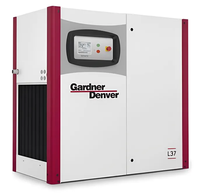
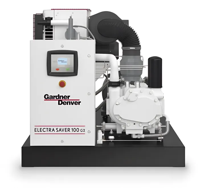
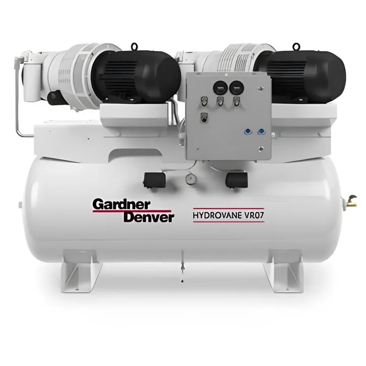

Most industrial compressors display both readings simultaneously. The tank gauge is mounted at or near the receiver vessel and reflects the current stored pressure. The regulator/outlet gauge sits downstream of the regulator and reflects the pressure tools actually receive.
What Is Tank Pressure?
Tank pressure is the PSI of compressed air stored inside the receiver vessel at any given moment. It isn't a single fixed value - it cycles within a range defined by the cut-in (start) and cut-out (stop) settings on the pressure switch. Cut-in is the lower threshold that starts the compressor; cut-out is the upper threshold that stops it. A portable rotary screw unit might cycle between 100 and 125 PSI, for example.
The pressure switch - not the regulator - governs this behavior. The compressor motor responds to the switch, cycling on when pressure drops to cut-in and off when it reaches cut-out. The safety relief valve is a separate, last-resort protection against over-pressurization, not an operational control.
How Receiver Tank Size Affects Pressure Behavior
Receiver volume directly affects how often the compressor cycles. According to CAGI's air storage brief, electric motors should start no more than 7 times per hour - excessive starts accelerate motor and pump wear. A larger receiver stores more compressed air volume, extending the time between cycles even during high demand.
CAGI provides practical sizing formulas:
- Added Storage (CF) = Gallons ÷ 7.48
- Drawdown Time = Added Storage ÷ Demand
- Pump-Up Time = Added Storage ÷ (Compressor Capacity − Demand)
These formulas are more useful than generic recovery-time rules of thumb, because recovery time varies with tank volume, pressure differential, compressor CFM, and simultaneous demand.
When Tank Pressure Settings Matter
Tank pressure decisions come up during system specification and design. Industries with high peak demand (automotive body shops, packaging lines, machine tool operations) need adequate cut-out pressure to avoid frequent short-cycling.
Tank pressure must also account for all the pressure losses between the receiver and the point of use. Downstream piping, fittings, filters, and dryers all create measurable pressure drop before air reaches any tool. The Comp-Air Ohio service team regularly works with facilities where ZEKS refrigerated dryers and filtration equipment add between 1.6 and 3.5 PSI of pressure drop depending on model capacity and flow conditions. Those losses must be factored into tank pressure settings from the start.
What Is Regulated Pressure?
Regulated pressure is the downstream PSI controlled by the pressure regulator: the actual working pressure delivered to a tool, spray gun, pneumatic cylinder, or process. The regulator is a pressure-reducing device only. It throttles airflow through an internal spring-loaded valve to hold a set downstream pressure steady despite fluctuations in tank pressure upstream.
Selecting the right regulator type for the application matters:
- General-purpose relieving regulators: Standard industrial air circuits; vent downstream pressure when the set point is reduced
- General-purpose non-relieving regulators: Applications where venting downstream air is not acceptable
- Precision regulators: Tighter tolerances for sensitive processes - SMC's IR series lists 0.2% full-span sensitivity and ±0.5% full-span repeatability
- Pilot-operated regulators: Controlled by external pilot air for large-flow or remotely managed pressure circuits
One important sizing note: select regulators based on CFM flow capacity, not pipe size. The Norgren R18 data illustrates why - at 101 PSI inlet and 91 PSI set pressure, that regulator shows 14.5 PSI of droop under specified flow conditions. An undersized regulator creates excessive pressure drop across the valve itself, defeating the purpose of regulation.
Verified Tool PSI Requirements
Running tools above their optimal regulated PSI doesn't improve performance - it accelerates wear, increases air consumption, and raises energy costs. Running below minimum PSI causes underperformance or failure.
| Tool / Application | Verified Operating Requirement |
|---|---|
| Pneumatic brad nailers (Metabo HPT NT50AE2, NT50A5) | 70–120 PSI |
| ½-inch impact wrench (CAGI) | 70–90 PSI at 4.0–5.0 CFM (intermittent) |
| Dental handpieces (Dentsply Stylus, KaVo SMARTtorque) | 40 PSI |
| Production paint spray guns (CAGI) | ~8.0 CFM (PSI per gun model specifications) |
For food packaging, pharmaceutical, and pneumatic cylinder applications, regulated pressure requirements vary significantly by equipment model. Always verify against OEM documentation rather than generic ranges.
How to Set the Right Pressure Differential
The pressure differential - the gap between tank cut-out pressure and the highest regulated pressure in the system - isn't arbitrary. It must cover real, measurable losses.
What the Differential Needs to Account For
Three separate loss categories reduce pressure between the tank and the tool:
- Distribution losses - CAGI recommends keeping air velocity at or below 20 ft/s in main headers to minimize turbulence. Each 90-degree elbow can add the equivalent of 25 feet of additional piping resistance
- Treatment equipment losses - filters and dryers create pressure drop at every installation. CAGI notes that each 1 PSI of filter pressure loss adds 0.5% to electricity consumption
- Regulator droop - the difference between set pressure and actual delivered pressure under flow conditions (verify from component data sheets, not general rules)
Step-by-Step Process for Setting Pressure Correctly
- Identify the highest PSI requirement among all connected tools and processes
- Measure or calculate distribution losses from tank to farthest point of use - account for pipe length, fittings, and bends
- Add treatment equipment pressure drops - pull specs from your dryer and filter documentation
- Factor in regulator droop under loaded flow conditions
- Set the regulator at the tool's required PSI; confirm against the tool manufacturer's specification
- Set cut-out pressure high enough to cover all the above, with room for the compressor's natural pressure swing during the cut-in/cut-out cycle

Validate regulator settings with the tool running, not at rest. Dynamic pressure guidance states that 90 PSI should be confirmed at the tool inlet while the tool is operating.
VSD Compressors and Tighter Pressure Bands
Variable Speed Drive (VSD) compressors handle pressure differently from fixed-speed models. Rather than cycling fully on and off, VSD units adjust motor speed to match air supply to demand - maintaining a much tighter pressure band. Industry data commonly shows fixed-speed load/unload bands around +/-0.3-1 bar versus VSD bands near +/-0.1 bar.
Operating at a narrower band lets VSD systems run at lower overall network pressure - and lower pressure means lower energy consumption. Key advantages in variable demand environments include:
- Reduced baseline pressure - no need to maintain high headroom for wide cut-in/cut-out swings
- 30–50% energy savings over fixed-speed units, per Gardner Denver LRS Series performance data
- Consistent delivery pressure that reduces wear on downstream regulators and tools

Multi-Zone Environments
Facilities running tools with different PSI requirements don't need to compress everything to the highest requirement. Individual point-of-use regulators at each drop allow each application to receive its correct pressure while the system maintains a single higher tank pressure. This prevents over-pressurization of sensitive equipment, reduces leak rates on lower-pressure circuits, and keeps operating costs from creeping up due to unnecessary system-wide pressure elevation.
What Happens When Pressure Settings Go Wrong
Insufficient Differential
When tank pressure is set too close to the regulated output pressure, the system can't sustain steady downstream pressure during demand peaks. The practical consequences:
- Tools lose power mid-cycle as tank pressure briefly dips below the regulated setpoint
- Production quality drops on pressure-sensitive processes
- The compressor short-cycles - CAGI sets the limit at no more than 7 motor starts per hour; frequent cycling beyond that accelerates motor and pump wear
Over-Pressurization Downstream
Running regulated pressure higher than tools require is a direct energy tax. According to the DOE FEMP, in 100 PSI systems, every 2 PSI increase in discharge pressure raises energy consumption by approximately 1% at full output flow. Across multiple shifts and multiple compressors, that percentage compounds into measurable cost increases month over month.
Higher pressure also amplifies leak losses. The Compressed Air Challenge estimates leaks waste 20–30% of compressor output, with annual costs at $0.05/kWh reaching $523 for a 1/16-inch leak and $8,382 for a 1/4-inch leak. Pressure directly scales leak severity.

Warning Signs That Settings Need Review
Both failure modes - insufficient differential and over-pressurization - tend to surface through the same observable symptoms before they show up on an energy bill. Watch for these diagnostic cues:
- Tools performing inconsistently across shifts
- Compressor cycling more frequently than expected
- Unexplained increases in energy costs
- Premature tool wear on components downstream of a regulator
- Pressure gauge readings that look fine at rest but drop under load
Any of these patterns is a signal to audit the system before assuming equipment failure. Comp-Air Ohio provides compressed air audits for Northern Ohio facilities to pinpoint pressure setting inefficiencies and recommend targeted corrections.
Conclusion
Tank pressure and regulated pressure serve distinct roles in the same system - one stores the supply, the other controls delivery. Getting that relationship right determines whether your tools receive consistent pressure, your equipment holds up under load, and your system runs efficiently every shift.
For Northern Ohio industrial facilities uncertain about their current pressure settings, Comp-Air Ohio's compressed air audit service evaluates the full system - from compressor controls through distribution losses to point-of-use delivery. Contact Comp-Air Ohio at (440) 237-6700 to schedule an assessment.
How Comp-Air Ohio Delivers for Your Plant
Comp-Air Ohio is the Gardner Denver air compressor dealer for Northeast Ohio, serving manufacturing plants, automotive shops, processing facilities, and commercial businesses from 9841 York-Theta Drive in North Royalton since 1977. Your Cleveland, Akron, and Northern Ohio facility gets local sales, service, repair, maintenance, parts, compressed air audits, and electric rentals up to 300 HP, plus all-makes repair when uptime matters.
Explore related resources on our compressors, parts, dryers, aluminum piping, lubricants, compressor controls, nitrogen generators, and used equipment pages.
Ready for next steps? Request a quote, call Cleveland at (440) 237-6700, Akron at (330) 928-3092, or toll-free at (800) 247-7978.
Frequently Asked Questions
What should air compressor tank pressure be?
For industrial reciprocating compressors, tank pressure typically falls between 100–175 PSI; oil-injected rotary screw packages can range from 50–250 PSI depending on the unit. The key requirement is that cut-out pressure must always exceed the highest regulated output pressure plus all line losses between the tank and the point of use.
How long should it take to build air pressure from 50 to 90 PSI?
Recovery time depends on tank volume, compressor CFM output, and simultaneous demand - there's no reliable universal benchmark. Unusually slow recovery is a diagnostic signal pointing to insufficient compressor capacity, excess demand, system leaks, or restricted treatment equipment rather than a normal operating condition.
Is 4 CFM at 90 PSI good?
CAGI rates a ½-inch impact wrench at 4.0–5.0 CFM at 70–90 PSI for intermittent use, so 4 CFM at 90 PSI covers light-duty intermittent work. That same tool at continuous load requires approximately 22 CFM. Suitability depends entirely on the tool's CFM requirement and duty cycle.
What happens when tank pressure is too high?
Excess tank pressure stresses seals, fittings, and downstream components, raises energy consumption, and scales up leak losses across every fitting and connection. If the regulator isn't set correctly, high tank pressure can also drive downstream pressure above the tool's rated range, accelerating wear.
Can regulated pressure ever exceed tank pressure?
No. A pressure regulator is a reducing valve only. If tank pressure drops below the regulator's set point, output pressure drops with it - the regulator cannot boost pressure beyond what the tank supplies.
How do I know if my pressure regulator is set correctly?
Check the tool manufacturer's recommended PSI range, then verify the regulator gauge reads within that range while the tool is running - not just at idle. Confirm that tank pressure remains sufficiently above the regulated setting throughout the full compressor cycle to cover line losses and regulator droop under load.